FANUC 9051/433 DC-link undervoltage: PSM display 4 alone does not justify replacement
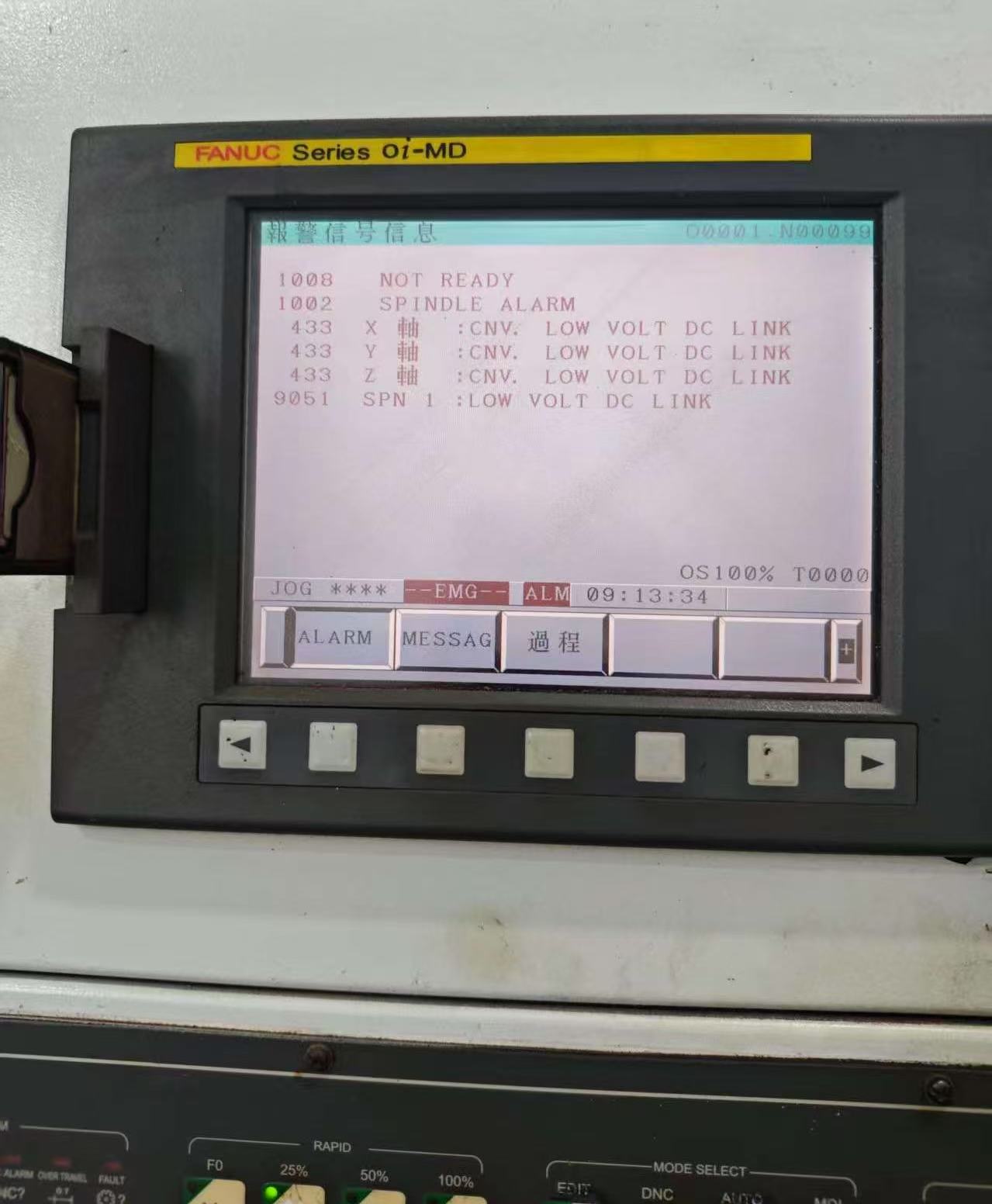
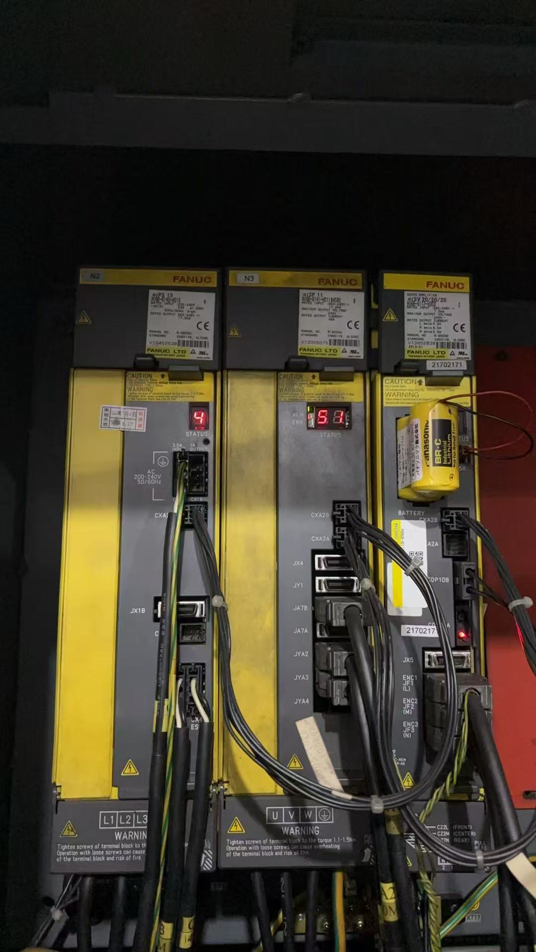
The αi-series manufacturer's manual is used to check the relationship between 9051, 433, SPM 51 and PSM 4. Original alarm photographs are retained, with an explanation of why undervoltage must be investigated alongside power conditions and shutdown order.
Contents
The site's original material records FANUC messages 9051, 433 and LOW VOLT DC LINK, and suggests observing power-supply amplifier display 4 and spindle amplifier display 51. It does not include complete equipment models, measured input-power conditions or a final repair outcome. The two original photographs therefore preserve the symptoms; they are not evidence that a power-supply module has been confirmed faulty.
Where these numbers correspond
In the applicable tables in section 2.2 of the FANUC αi Series Maintenance Manual B-65285EN/03, 433 denotes converter DC-link undervoltage; 9051 corresponds to SPM display 51 and PSM display 4. Section 3.1.4 describes PSM/PSMR alarm 4 as a drop in main-circuit DC voltage and lists checks such as a brief voltage dip, low input voltage, or main power being disconnected when emergency stop is released. This does not automatically confirm applicability to every hardware revision in the site's photographs.
First establish which symptoms occurred together
Save the complete NC alarm and each relevant module's model and panel display, noting whether several axes alarmed together. Specify the stage: normal running, power-on, after emergency-stop release, or shutdown and power-off. In particular, determine whether the alarm occurred before main power was disconnected or vice versa. The last message observed must not simply be taken as the initial cause.
Both supply conditions and control sequence need evidence
Operators can first provide power-interruption records, recent electrical changes and the actual sequence of events. Electrical maintenance personnel should check input conditions, contactor state and relevant measurements against the machine's circuit diagram and applicable manual. Without measured evidence, do not write that the supply has been confirmed normal, or replace the PSM without investigating the input conditions.
The main circuit stores high-voltage energy. This article gives no procedure for probing energized terminals, bridging contactors or suppressing alarms. If tripping, burn marks or abnormal sounds are also present, stop repeated attempts, preserve the information and arrange inspection.
How to reach a conclusion that can be checked
Record actual measurements, work performed and alarm changes on the same job sheet; leave unfinished checks marked as awaiting confirmation. After repair, restart under the machine-level procedure and retain the verification results. One power-on without an alarm does not establish that the fault has been eliminated. Those conclusions were not in the site's original record, and this revision does not invent repair results.
If the screen actually indicates overcurrent, compare the 9012 main-circuit overcurrent record (Chinese); for an overall power-supply error, consult the SP9201 site record (Chinese). Each alarm requires its own model-specific manual; troubleshooting methods are not interchangeable.
Original site photographs
Reference: FANUC αi Series Maintenance Manual, B-65285EN/03, §2.2.1 and §2.2.2, pages 81 and 83; §3.1.4, page 87; public mirror hosted by Nex Instrument. This article explains applicability and suggests how to organize site information. Perform specific work according to the documentation for the actual equipment and its machine builder.